The Wenger Showmobile
Model 6432 H
Basic Instructions
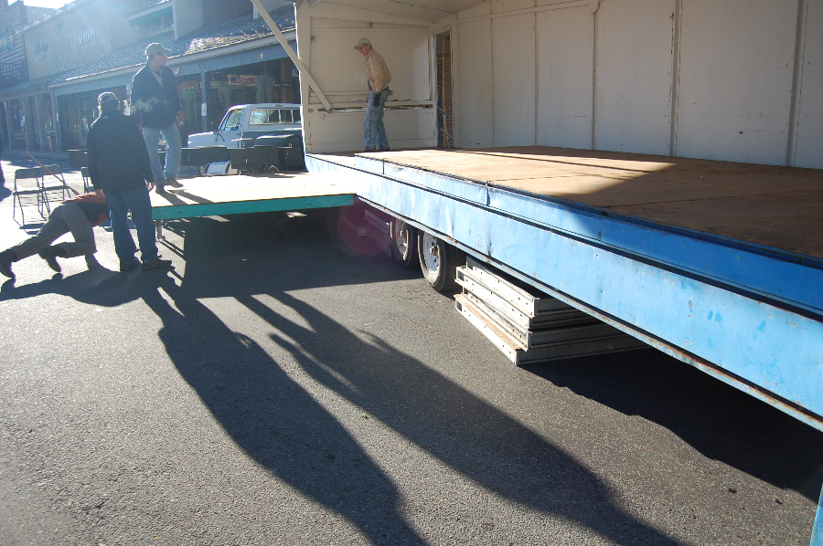
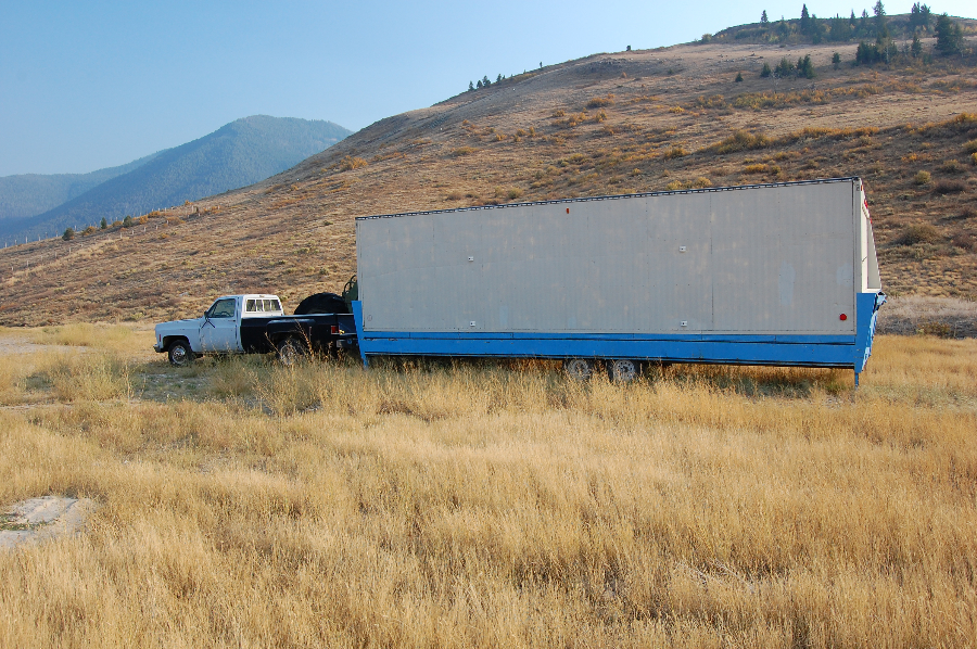
The extension panels weight between 90-120 lbs each, at least TWO people are necessary for handling them, and 3-4 make it easier and safer. The panels are 4' by 8', and there are 8 per layer. The trailer is 8' wide by 32' long (interior measurement), and there are TWO sets of stage extensions plus a conductor's panel. One row sits flat on the floor of the trailer. We only need one row of extensions for an average gig. When restoring them to the inside of the Showmobile after the gig, it's important to make sure that the first one is placed snugly against the side wall and the back wall, or else there may have to be a massive re-do when the last one won't quite fit.
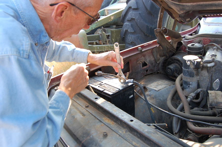
Disconnect the battery for winter storage. It is advisable to go to refuge a day or two prior to transport to get truck started.
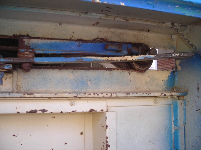
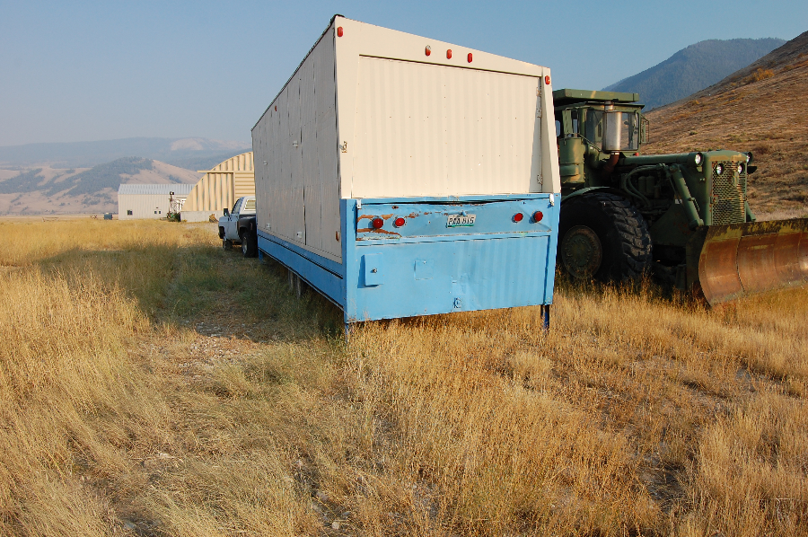
Back of trailer. Glide wheel in closed (transit) position. Horizontal steel bar/lever (blue on left side of it, rusty on outer right end) presses the "brake" in place during transit and storage. The brake (see pic. #1) is hidden behind this lever.
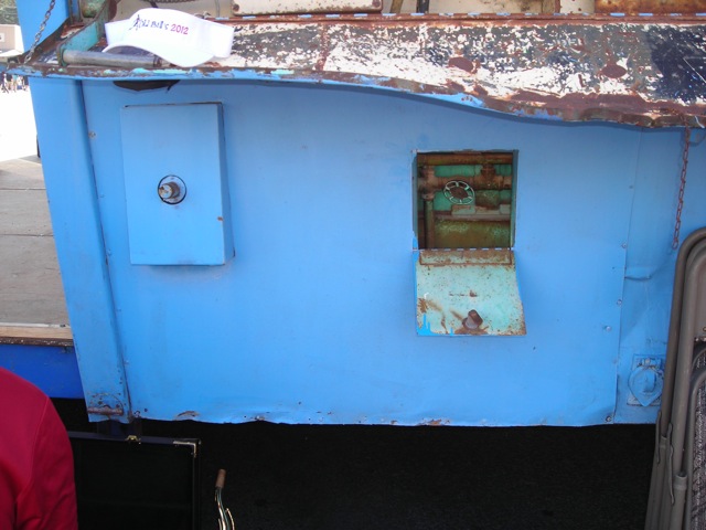
Square door open (any small key or a screwdriver will open that lock). Hydraulic system valve. Must be closed (turn to the right) to activate roof-lifting process with hydraulic pump running. To retract roof, pull the safety pins (one at each end of the trailer) and slowly open the valve. Gravity will close the roof. It's best to close the valve again after closing the roof, so that the next opening process will not be delayed by someone forgetting to close this.
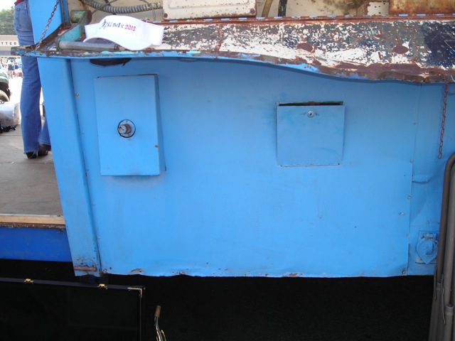
Back of trailer (stage extends to left). Notice crank on "shelf" at top of picture. Below it is the spline for attaching, if there is no electricity available to activate the hydraulic pump. Notice that square door to the right that will have an open view in another picture -- contains valve for hydraulic system that must be closed to activate the roof-lifting action. At bottom right (nearly obscured by chairs leaning against trailer) is the 120-volt access. Extension cord with special connection stays inside the trailer during storage.
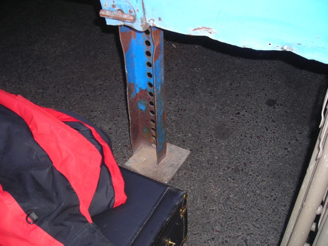
Corner stabilizer, back of trailer, "stage" side. Notice bends; may need some force to extend and to retract.
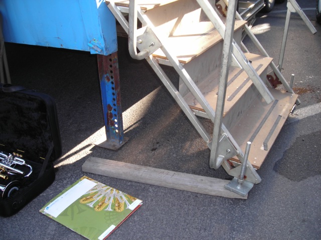
Access steps -- one set at each end of trail; hook into trailer at top of steps. Also shows corner stabilizer extended; pull top pin to retract for transit
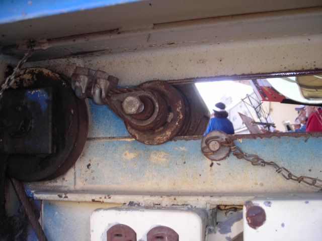
Glide wheel in open position (back of trailer) w/safety pin in place (connected to chain) 4. Access steps -- one set at each end of trail; hook into trailer at top of steps.
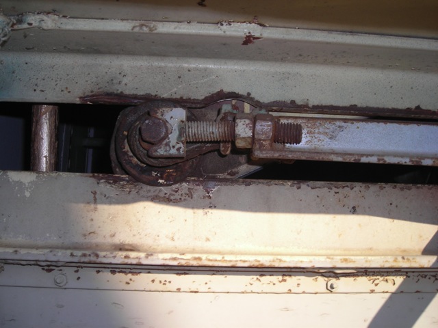
Front end of trailer -- "brake" in place to hold roof locked closed during transit. Notice extended axle of the glide wheel and the small steel plate (at left end of threaded bolt). See explanation in #9 below for the closing/locking and release of that safety mechanism. Lever pictured in #9 is not pictured in #1.
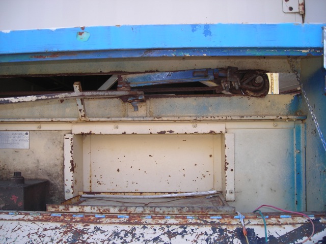
Same mechanism as in previous picture, but the closing lever is open (swung to the left in this shot), and the U-notched end of the "brake" is poised to be clamped behind the glide wheels axle that extend toward us with the cable wrapped around it. As the lever is closed from the left, that U-shaped notched end must be secured on that axle to fully clamp the roof closed for transit and storage. There is mirrored mechanism on the front end of the trailer. (See pic. #1.)
Contacts:

